
Intro
Hello Everyone!
We’re trying to be better at dev diaries and we hope you appreciate the info. Today we will be talking about aircraft in Sea Power and how they work behind the scenes.
The first thing to say is that Sea Power is not a flight simulator, it is focused around Naval Warfare in the Missile Age, but aircraft are a vital component of that. Because of that Sea Power does not give you direct control of flying individual aircraft like DCS or Flight Simulator but instead allows you to task single aircraft or formations to complete objectives and the pilots and squadron leaders will sort that out for you. Because Sea Power isn’t a traditional flight simulator we are able to play a little bit fast and loose with the physics of the aircraft that you see in the sky, which is sorely needed given the number you might have!
Flight Model
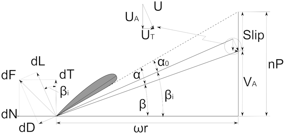
A traditional flight simulator implements a flight model with normally 6 degrees of freedom and will use complex analysis methodologies like the Blade Element Model (X-Plane famously uses this method) which I barely remember from University. These methods produce reliable and interesting flight dynamics but are computationally quite intense! Here for example we can see the model for a single element of a blade, imagine doing this for 40 to 50 elements per aircraft!
To save your computers from a fiery death Sea Power instead mainly (but more on that in a moment) implements a 3 Degree of Freedom model. Happily in the team we have access to people who have been trained in both Physics and Air Vehicle Systems, if you saw our interview with Subsim a number of weeks back we mentioned how nice it was to have a variety of backgrounds in the team and this is one of the places where this really really helps!
The model itself is based on the one described in this paper by Dr. Lesley A. Weitz and allows us to have a simple but rapid simulation for most of the flight envelope. The model allows us to provide control inputs based solely on Altitude, Heading, and Velocity values which means we can skip the weightier implementations using Unity’s physics system.
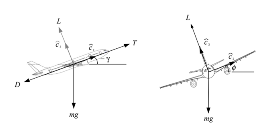
Additionally, as Dr Weitz has been kind enough to provide us with a set of control laws and dynamics in a set of pseudo-code algorithms a lot of the significant work is done for us, this gives us a solid base on which to build.
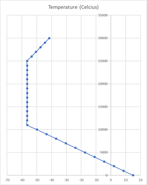
Part of that building has been implementing semi-realistic thrust and lift modelling to our model, at the very core of this is a model of the atmosphere. Sea Power makes use of the International Standard Atmosphere (ISA) as defined in this resource kindly provided by NASA. The ISA defines how the atmosphere changes around us and helps explain why the outside air temperature at 30,000 ft is significantly below 0C.
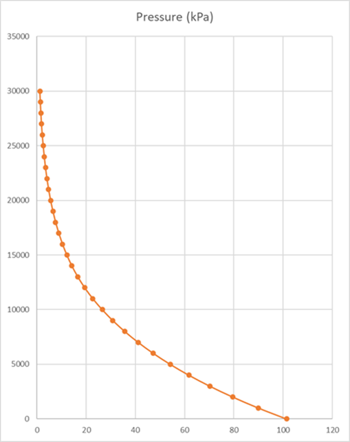
Alongside the temperature the pressure of the atmosphere significantly reduces with altitude, dropping from approximately 101.3 kPa at sea level to near 0 kPa at 30000m. Because the atmosphere nearly follows the ideal gas laws the density of the air reduces at the same time, this allows us to model the impact of altitude upon our aircraft.
Now for those of you that are familiar with this stuff I apologise but for those that aren’t welcome to the wonderful world of aerodynamics, operational analysis and propulsion physics. It almost makes me nostalgic for University again. Density has an important impact on our aircraft in two primary ways.
The first way is Dynamic Pressure, dynamic pressure is a measure of the energy in the air that impacts upon something, the force you feel pushing against your hand out the window of a moving car is Dynamic Pressure. We calculate it as dynamicPressure = 0.5 * density * velocity * velocity and it is important as both the Lift and the Drag of an aircraft depend on the product of dynamic pressure and lift and drag coefficient respectively. Fundamentally what this means is that the faster you go and the higher the air density the more lift and drag you get out of an aircraft.
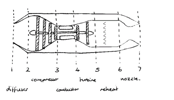
The second way drag impacts an aircraft is in the amount of thrust you can get out of its engine. Propulsion was one of my favourite modules at university and I have dug into my university notes to provide you these charming (yes that is my handwriting, can you tell why I am an engineer?) diagrams of the sections of a turbojet engine and a turbojet engine with reheat.

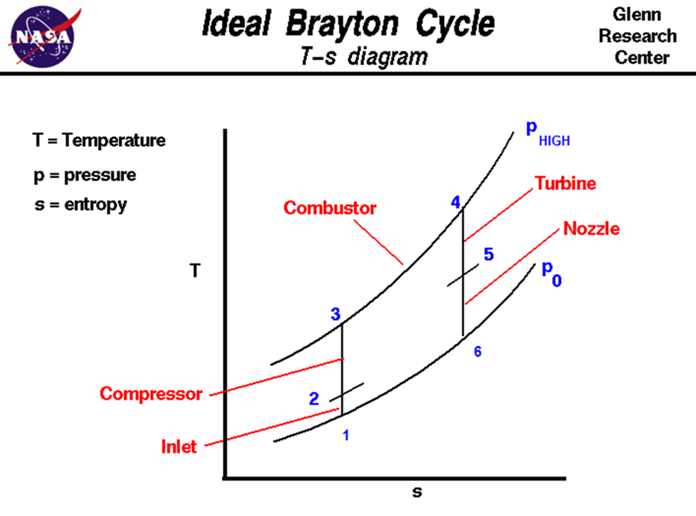
We use diagrams like this to visualise the propulsion cycle of the engine, shown in this diagram from NASA, which allows us to do a load of fancy derivations to arrive at a really simple equation for the thrust of an engine T = massFlowRate * (exhaustVelocity – inletVelocity) if we make a bunch of assumptions about the nature of life, the universe, and everything we can say that the Mass Flow Rate is the product of the inlet area, the velocity of the aircraft, and the air density. This means that thrust is directly linked to altitude! The equations get more complicated as we go to different engine types but the core of the problem is the same, Force = mass * acceleration, Isaac Newton to the rescue!
All of this leads us to something that looks pretty good and is computationally fairly simple (which is good as we can check the values with hand calculations) which we use for the majority of the life of an aircraft.
The details above allow us to force our aircraft to generate contrails, engine smoke, and tip vortices based upon the performance that you are demanding from them at a given moment.
Different States
However this doesn’t cover all scenarios, while the aircraft is not airborne we use a different controller for motion.The ground based controller is a really simple Newtonian system based upon the good old equation F=ma. We tend to ignore a lot of the realities on the ground in favour of getting you in the air quickly!
However the simple formula Isaac Newton gave us does not cover such trivial realities as navigating your way around an airbase, for that we use defined taxiways to allow you to watch your aircraft drive around on their way to the runway.

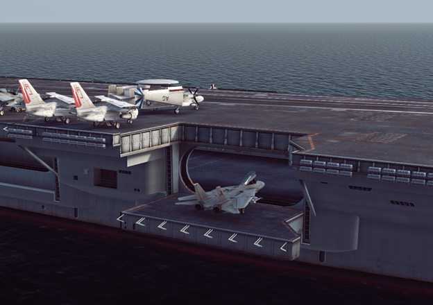
The same also applies to aircraft carriers, where the taxi paths are described in such a way as to allow unlimited possibilities (I know someone is already planning to launch their Vipers from the Battlestar Galactica). We have made sure to include details like opening and extending hangars and even oddities like the vertical elevators on the
Moskva-class Helicopter Cruiser.
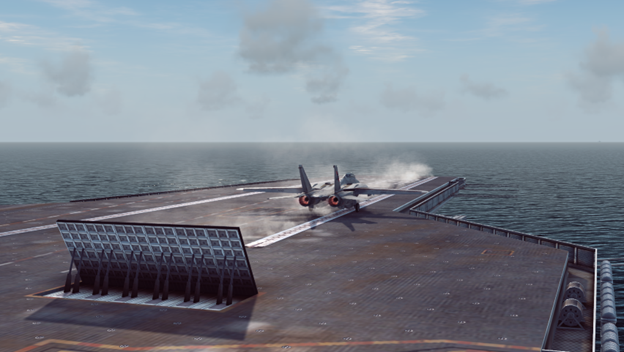
Takeoff is another situation where the normal flight model does not apply. Seapower supports, at present, 5 different types of takeoff: Normal, Catapult, Skijump, VTOL, and Helicopters. Each of these methods has its own system that allows us to provide realistic looking behaviour without risking the flight model getting horribly confused and smashing all of your shiny F-14s into a thousand tiny pieces.
These unique states exist throughout the flight control system and allow the aircraft to behave in a manner that is appropriate to the moment that they are in.
State Machines
A moment ago I referred to something called “states” this leads us to a really important concept for Seapower, and lots of games in general! This is the “Finite State Machine”. A State Machine is a way of creating a system that transitions through behaviour in a repeatable and reliable way when certain conditions are satisfied.
FSMs are used throughout Seapower to drive systems across a range from torpedo homing to aircraft landing, they are an incredible tool, if you want to learn more I recommend this video: Unity Bots with State Machines – Extensible State Machine / FSM – YouTube
Conclusion
At this point my ramblings have hit about 7 pages in Word so I think I better stop and get back to coding. We are really looking forward to getting this game to everyone who is out there waiting for it. We really can’t wait for you to see the effort and dedication that has gone into this across the last few years.
Here are two more videos showing landings on a carrier and on an airfield: